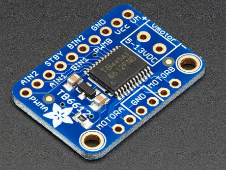
Hi all, I've wired a stepper motor to a TB6612 stepper motor driver which is in turn connected to a Raspberry Pi. An image of the stepper motor driver is given below.
![Image]()
The wiring is as follows.
VM ---> +12V power supply (the adapter used for this can supply up to 1.5A)
GND ---> GND
VCC ---> 5V in Raspberry Pi
GND ---> GND
PWMB ---> 5V in Raspberry Pi
BIN2 ---> D21
BIN1 ---> D20
AIN1 ---> D19
AIN2 ---> D26
PWMA ---> 5V in Raspberry Pi
MOTORA ---> stepper coil (red and yellow stepper wires)
MOTORB ---> stepper coil (green and grey stepper wires)
I've been using the code from adafruit (https://github.com/adafruit/Adafruit_Ci ... gitalio.py). It has been edited to try a number of different delays to see whether there is any change to the rotation. The edited code is given below:
The specifications for the motor are as follows (it is a bipolar stepper motor used as part of a peristaltic pump):
Power input: 12V DC
Step: 810 PPS
I've added a picture of the motor as well. It has some additional information.
https://postimg.cc/nsQMHPH4
Problem is that the motor doesn't rotate. It just vibrates a bit. On top of that, the driver module's IC heats up a lot and on two occasions, they simply broke. I've checked all the wiring, looked and conductivity, used different motors, used a different breadboard, and even used new driver modules, but I keep getting the same issue. Is my problem with the code? Or is there any other place I need to look at? I can provide additional information if needed.
The wiring is as follows.
VM ---> +12V power supply (the adapter used for this can supply up to 1.5A)
GND ---> GND
VCC ---> 5V in Raspberry Pi
GND ---> GND
PWMB ---> 5V in Raspberry Pi
BIN2 ---> D21
BIN1 ---> D20
AIN1 ---> D19
AIN2 ---> D26
PWMA ---> 5V in Raspberry Pi
MOTORA ---> stepper coil (red and yellow stepper wires)
MOTORB ---> stepper coil (green and grey stepper wires)
I've been using the code from adafruit (https://github.com/adafruit/Adafruit_Ci ... gitalio.py). It has been edited to try a number of different delays to see whether there is any change to the rotation. The edited code is given below:
Code:
import timeimport boardimport digitaliofrom adafruit_motor import stepper#DELAY = 0.0005DELAY = [0.01,0.001225,0.0008,0.0005,0.00009]STEPS = 10000#To use with a Raspberry Pi:coils = ( digitalio.DigitalInOut(board.D19), # A1 digitalio.DigitalInOut(board.D26), # A2 digitalio.DigitalInOut(board.D20), # B1 digitalio.DigitalInOut(board.D21), # B2)for coil in coils: coil.direction = digitalio.Direction.OUTPUTmotor = stepper.StepperMotor(coils[0], coils[1], coils[2], coils[3], microsteps=None)for x in DELAY: print(x) print("C") for step in range(STEPS): motor.onestep(style=stepper.DOUBLE) time.sleep(x) print("D") for step in range(STEPS): motor.onestep(direction=stepper.BACKWARD, style=stepper.DOUBLE) time.sleep(x)Power input: 12V DC
Step: 810 PPS
I've added a picture of the motor as well. It has some additional information.
https://postimg.cc/nsQMHPH4
Problem is that the motor doesn't rotate. It just vibrates a bit. On top of that, the driver module's IC heats up a lot and on two occasions, they simply broke. I've checked all the wiring, looked and conductivity, used different motors, used a different breadboard, and even used new driver modules, but I keep getting the same issue. Is my problem with the code? Or is there any other place I need to look at? I can provide additional information if needed.
Statistics: Posted by chamathkv — Thu Oct 24, 2024 8:53 am — Replies 1 — Views 22